Linear rail guides are designed for applications that call for precise motion with high load-bearing capability. But improper mounting can add unnecessary loads, reduce life, and undermine the inherent travel accuracy of the linear guide system. Understanding and following the three mounting specifications described below will help ensure your THK linear guide installation achieves the desired accuracy and doesn’t succumb to premature failure.
Rail Parallelism
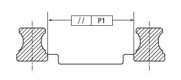
The most common installation of linear rail guides is a two-rail, four-carriage arrangement. But regardless of the number of carriages, when two rails are used in parallel, extra side loads can result if they are not mounted within the manufacturer’s specified parallelism tolerance, often denoted as P1. There are many options for securing the rails and ensuring their straightness, ranging from the most precise method using a machined reference edge for each rail, to the least precise (and least costly) method of mounting one rail using a straight edge or gauge, and using a connecting plate to “float” the second rail into proper alignment.
It’s important to note that if the rails are not mounted against a reference edge or retaining strip, the permissible side forces may be reduced. This is because when there is no lateral retention, the sheer strength of the rail mounting screws becomes the limiting factor for the permissible side load.
Vertical Offset Between Rails
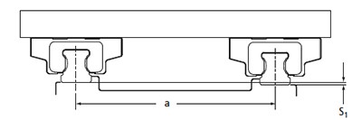
Rails used in parallel should also adhere to the maximum permissible offset in the vertical direction. This is often specified as S1, and is a function of the distance between the rails and the preload of the carriages—the higher the preload level of the carriages, the smaller the permissible vertical offset. If this value is exceeded, a roll moment will be introduced into the carriages, which can result in shortened bearing life.
When calculating the vertical offset, the height tolerance, H, of the carriages must be taken into account. If the inclusion of the height tolerance causes a greater offset than is permissible, carriages with either lower preload or higher accuracy should be used.
Vertical Offset Between Carriages

When multiple carriages are used on the same rail, the vertical offset between carriages, often denoted as S2, becomes an important factor and can impart a pitch moment on the carriages. The permissible vertical offset is a function of both the length of the carriages (standard, short, or long) and the distance between carriages.
Similar to the offset between rails, the calculation of vertical offset between carriages should take into account the height difference between carriages, ΔH. If the actual vertical offset is greater than the calculated permissible offset, S2, then a shorter version of the carriages, or a higher accuracy version, must be used.
Of course, proper mounting involves other factors, many of which aren’t directly related to the components being used, such as base preparation, the geometry of reference edges, and even the procedure for tightening the mounting screws. And less-demanding applications can often perform satisfactorily with less-stringent mounting procedures. But for the most critical and highly accurate THK linear rails installations, closely following the manufacturer's specifications for mounting and installation will ensure the highest accuracy possible and avoid reducing the life of the system.
Questions or comments about a THK linear guide installation? Call our motion control distributors at 330-847-7000 or contact us online today for all over your linear motion requirements.

